 Display Assembly
Dell™ XPS™ M1210 Service Manual

|
CAUTION: Before you begin the following procedure, follow the safety instructions in the Product Information Guide. |

|
NOTICE: To avoid electrostatic discharge, ground yourself by using a wrist grounding strap or by periodically touching an unpainted metal surface (such as the back panel) on the computer. |

|
NOTICE: To help prevent damage to the system board, remove the main battery (see Before Working Inside Your Computer) before working inside the computer. |

|
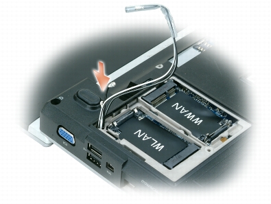
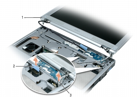
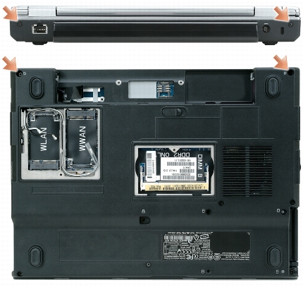
NOTE: You must detach the Mini-Card (WLAN and/or Mobile Broadband) antenna cables (see step 3) before you can remove the display assembly. If a Mini-Card is installed, disconnect the antenna cables from the card(s). If one is not installed, detach the antenna cables from their secured location. |
|
1 |
display assembly |
2 |
pull-tab on display cable |
3 |
Mini-Card antenna cables |

|
NOTICE: When removing the display assembly, carefully unthread the Mini-Card antenna cables through the computer base and ensure that the plastic protectors—if present—remain on the individual cables. |

|
NOTICE: When replacing the display assembly, ensure that the plastic protectors—if present—remain on the individual Mini-Card antenna cables. |
|
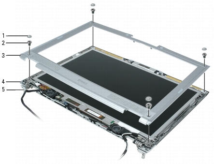
1 |
rubber bumper/screw covers (4) |
3 |
display bezel |
|
2 |
M2.5 x 5-mm shoulder screws (4) |
4 |
display back cover |
|
5 |
hinge pins (2) |
|
|

|
CAUTION: Before you begin the following procedure, follow the safety instructions in the Product Information Guide. |

|
NOTICE: To avoid electrostatic discharge, ground yourself by using a wrist grounding strap or by periodically touching an unpainted metal surface (such as the back panel) on the computer. |

|
NOTICE: To help prevent damage to the system board, remove the main battery (see Before Working Inside Your Computer) before working inside the computer. |

|
NOTICE: Removal of the bezel from the display back cover requires extreme care to avoid damage to the bezel and the display panel. |

|
NOTE: To facilitate replacement of the display bezel, ensure that the camera connector is tucked in place beside the display panel before you snap the bezel into place. |
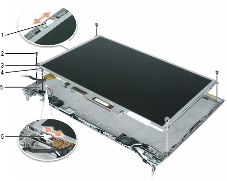
|
1 |
camera cable connector (present only on computers with an optional camera) |
3 |
display panel |
5 |
display back cover |
|
2 |
M2 x 3-mm screws (4) |
4 |
M2 x 3-mm display-cable ground screw and ground wire |
6 |
speaker cable |

|
CAUTION: Before you begin the following procedure, follow the safety instructions in the Product Information Guide. |

|
NOTICE: To avoid electrostatic discharge, ground yourself by using a wrist grounding strap or by touching an unpainted metal surface (such as the back panel) on the computer. |

|
NOTICE: To help prevent damage to the system board, remove the main battery (see Before Working Inside Your Computer) before working inside the computer. |
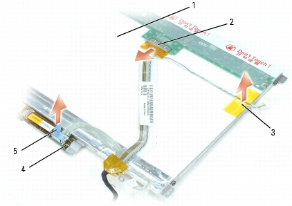
|
1 |
back of display-panel cable assembly |
3 |
tape holding camera cable in place |
5 |
pull-tab on inverter connector |
|
2 |
top flex-cable connector |
4 |
bottom flex-cable connector |
|
|

|
CAUTION: Before you begin the following procedure, follow the safety instructions in the Product Information Guide. |

|
NOTICE: To avoid electrostatic discharge, ground yourself by using a wrist grounding strap or by touching an unpainted metal surface (such as the back panel) on the computer. |

|
NOTICE: To help prevent damage to the system board, remove the main battery (see Before Working Inside Your Computer) before working inside the computer. |
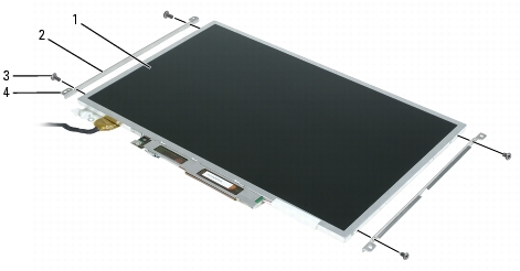
|
1 |
display panel |
3 |
M2 x 3-mm screws (4) |
|
2 |
display-panel brackets (2) |
4 |
tabs on display-panel brackets (4) |

|
NOTICE: Ensure that you attach the display-panel brackets to the display panel such that the tabs are flush with the display panel surface. |